
The mirror cell is an 18 point flotation design built to the specifications from Berry and Kreige. The only departure is in the design of the strap.
The spreaders and triangles of the floating cell are machined from 316 stainless steel. Something I will not do again by choice. The alloy was extremely tough and in the process I ruined a carbide end mill. But in the end I managed two sets of parts.
The 1" wide spreaders were done to the dimensions given in Berry and Kriege. I have decided that they are too narrow. Mine had begun to bend under the weight of the primary, especially during transport. These have been replaced with wide aluminum spreaders.
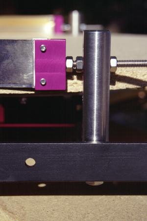
I had to shorten the middle/lower collimation bolt. The bolt brushed the top of the azimuth encoder and I just didn't need that much adjustment range.
The collimation bolt interference could be easily solved by arranging the bolts with the two bolts on the lower rung, this would allow the rocker box to be roughly 2cm (1 inch) shorter and more compact. This would also lower the eyepiece an equal distance closer to the ground. The spacing of the rungs and other dimensions would have to be changed to do this.
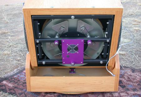
With the cell turned over you can see the cooling fan and the collomation bolts. With more of the violet anodized aluminum that gives the scope its name.
The strap is a piece of beryllium copper alloy surplused from an engineering project I worked on. It was intended for stamp forming of battery charger contacts. It is very flexible, has little thermal mass as it is only 0.020in. thick and does not stretch.
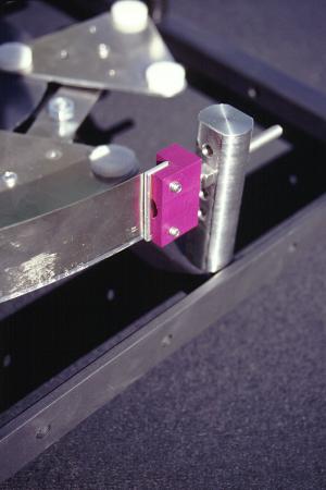
The strap is held in place with two machined stainless steel posts with a 1/4-20 adjustment screw holding the end of the strap. To hold the thin metal of the strap I folded it around a thicker piece of aluminum and put two machine screws through both. This arrangement allows adjustment of the strap length to center the mirror in the cell.
The end result is a mirror cell that holds the mirror with no visible distortion. I have star tested the telescope and any flexing of the mirror should have been visible, but none is seen. I am going to attempt to photograph the defocused star images. The plan is to use polaris to overcome the lack of a drive.
As of Sep 2002 I had solved (at least for now) the problem of the bending spreader bars by taking the set from the second mirror cell and doubling them up with the old ones. At the same time flipping the old ones over so that the bend was upwards. New wide aluminum spreaders have been manufactured for both scopes.
I also cut the lower collimation bolt 1cm shorter while I had everything apart. It no longer interferes with the azimuth encoder.